

A quick visual guide
Height & Bump Map Generator
01Input
Turn image brightness into a working height or bump map, or start with repeatable procedural noise. Adjust the grayscale, inspect the result and export a real PNG. One grayscale workflow for height and bump. Local processing, a useful sample and no upload. The output describes relative values; it does not recover measured surface depth.
02Adjust
Start with the synthetic reference or open a PNG, JPEG or WebP. Use Procedural mode when you want a repeatable pattern rather than an image-derived estimate. Set black and white points to choose the working range. Gamma changes the midtones; blur softens fine variation; invert swaps high and low values. Download the grayscale map. In your material application, connect it to the intended bump or displacement input and check data colour space, strength and scale.
03Check the result
A bump shader can use differences in a grayscale height texture to change the shading normal. Displacement can move the surface when the material, renderer and geometry support it. The same map does not produce the same result in both inputs. Image brightness contains colour, lighting and shadows. A dark patch may be paint rather than a recess. This tool uses an encoded-RGB brightness approximation and exports opaque 8-bit grayscale, so subtle gradients may band. Use a higher-bit-depth workflow for a final displacement master when needed. Procedural endpoints match before further processing; always inspect the repeated result, especially after blur.
Open each step for the practical check. Diagram, not a generated result.
XO3D Labs / Material workshop
Height & Bump Map Generator
Turn image brightness into a working height or bump map, or start with repeatable procedural noise. Adjust the grayscale, inspect the result and export a real PNG.
One grayscale workflow for height and bump. Local processing, a useful sample and no upload. The output describes relative values; it does not recover measured surface depth.
Build a height map you can inspect.
- Start with the synthetic reference or open a PNG, JPEG or WebP. Use Procedural mode when you want a repeatable pattern rather than an image-derived estimate.
- Set black and white points to choose the working range. Gamma changes the midtones; blur softens fine variation; invert swaps high and low values.
- Download the grayscale map. In your material application, connect it to the intended bump or displacement input and check data colour space, strength and scale.
Read the output correctly
A bump shader can use differences in a grayscale height texture to change the shading normal. Displacement can move the surface when the material, renderer and geometry support it. The same map does not produce the same result in both inputs.
For a dark-to-light reference, identity levels preserve the working brightness. Black point 64 and white point 192 clip the ends and spread the middle values across the available range. A higher gamma lifts the middle; it is not a measurement of extra surface height.
Limits and next checks
Image brightness contains colour, lighting and shadows. A dark patch may be paint rather than a recess. This tool uses an encoded-RGB brightness approximation and exports opaque 8-bit grayscale, so subtle gradients may band. Use a higher-bit-depth workflow for a final displacement master when needed. Procedural endpoints match before further processing; always inspect the repeated result, especially after blur.
Updated 4 November 2026 by XO3D Labs
Height map generator from an image: what the map means
This tool turns a photo or texture into a grayscale height map for material surface detail, such as bump and displacement. It does not build terrain. It reads the brightness of your image as relative height, so the map is a starting point to check, not a measurement of the surface.
From source brightness to relative height
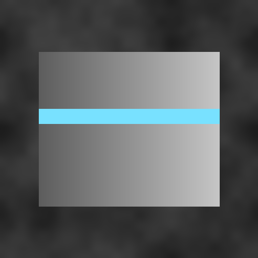
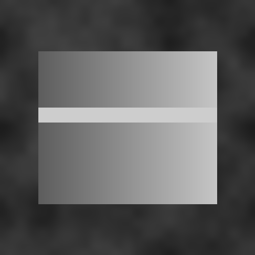
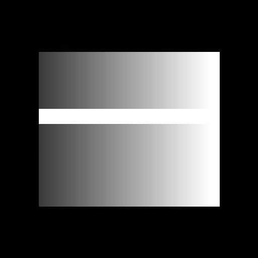
We loaded the tool's own synthetic sample on 4 November 2026 and exported the map twice: at the default settings, and with black point 64 and white point 192. The tool takes the brightness of each pixel (0.2126 red + 0.7152 green + 0.0722 blue, on the stored values) and writes it as a grey level from 0, lowest, to 255, highest.
At the defaults the map equals that brightness. The panel ramps from about 93 on the left to 197 on the right, and the background sits between 28 and 66. The thin cyan stripe is only colour, but its brightness is 205, so the map treats it as the highest ridge on the panel. With black 64 and white 192, values at or below 64 become 0 and values at or above 192 become 255: the background drops to black, and the panel now runs from 58 to 255, with its right-hand end clipped to white.
What the export contains
| Input | PNG, JPEG or WebP, up to 20 MiB (the tool's message says 20 MB) and 64 million pixels |
|---|---|
| Working size | Reduced to fit 1024 px on the longest edge; smaller images keep their pixel size. The caption under the source says when an image was reduced |
| Procedural mode | A square of 256, 512 or 1024 px |
| Transparency | Placed over black before the brightness is read |
| Download | An opaque 8-bit grayscale PNG named xo3d-height-map.png, at the working size |
| What it is not | A measured displacement master. There is no 16-bit option |
Read from the tool's own script on 4 November 2026. The status line repeats the size of the PNG it prepared.
Choose a useful source
The tool cannot tell shape from colour or light. Give it a source where brightness mostly follows the surface you want: a front-facing view, even light, no strong shadows or highlights, no painted marks or printed lettering, and as little compression noise as you can. A height or bump map painted on purpose is the most reliable input of all.
The diagram shows why. A raised bump lit from one side is bright on one half and dark on the other, so it reads as a tilted patch, not a dome. A flat, dark painted spot reads as a hollow. Invert flips every value at once, so it cannot fix one false hollow while keeping a real bump: correct that area locally in the source image instead.

What levels and gamma change
The controls run in a fixed order: blur first, then the black and white points, then gamma, then invert. Reset levels returns black 0, white 255, gamma 1, blur 0 and invert off, which leaves the brightness unchanged.
Black and white points choose the working range. Values at or below the black point become 0, values at or above the white point become 255, and everything between is stretched across the full range. The 64 and 192 example above clips both ends and spreads the middle. It changes how the existing values are spread; it does not add height.
Gamma bends the midtones while keeping 0 and 255 in place. Above 1 it lifts them: with gamma 2, a value of 128 becomes 181. Below 1 it lowers them. Blur averages each pixel with its neighbours over a radius of 0 to 16 px. It suppresses noise and compression blocks, and it also softens fine detail and edges, so there is no single best value: compare the result at the size the map will be seen.
Use the map in the intended input
The same grayscale map behaves differently depending on where you connect it. Height is data, not colour, so check how the destination reads the image's colour space before judging the result.
| Input | What it does | Check |
|---|---|---|
| Bump | Changes the shading normal from differences in height. The surface does not move | Strength and distance in the shader; artefacts where the real shape differs a lot |
| Displacement | Moves the surface, if the renderer and material support it and the mesh is finely subdivided | Scale and midpoint settings in your renderer; whether 8-bit steps show |
| Normal map | A separate map made from the height map, used for shading | Turn a height map into a normal map, then check its direction convention |
The Blender manual describes the Bump node and bump versus displacement: bump changes only the shading, true displacement needs a finely subdivided mesh, and 16 or 32-bit float maps give better displacement than 8-bit. Read 4 November 2026. Other renderers have their own settings.
A bump or normal map cannot change the silhouette. If the outline must change, use displacement on suitable geometry, or model the shape. Need the other maps too? Make a full set of material maps.
Inspect the repeated result
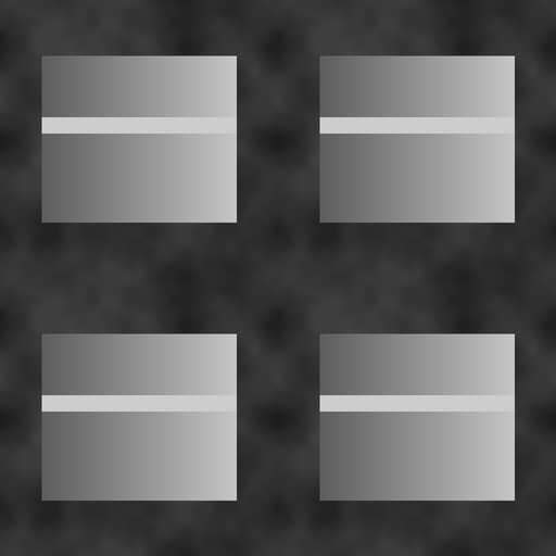
If the map will tile, check it repeated. The 2 x 2 view below repeats the default sample map. Its background comes from the tool's procedural noise, whose opposite edges match, so the joins do not show, but the panel repeats as a regular grid. A repeat view shows breaks at the joins; it does not show whether the surface heights are accurate.
Blur does not wrap around the edges of the image: near an edge it only averages pixels inside the image. So a map whose edges matched before blurring can gain a visible join. Check the repeat boundary after blurring.
Guides for this tool
- Bump, normal or displacement?
- Keep material maps consistent between tools
- Prepare product finishes with deliberate roughness and metalness
Frequently asked questions
Does this recover real depth from a photo?
No. It reads the brightness of each pixel and treats it as relative height. Lighting, shadows and paint are read the same way, so the map shows what the image looks like, not how deep the surface is.
Is this a terrain heightmap generator?
No. It makes grayscale height and bump maps for material surface detail. For other material maps from a photo, use Image to PBR.
Does it export 16-bit?
No. The download is an opaque 8-bit grayscale PNG, so very gentle gradients can show steps. Use a higher-bit-depth workflow for a final displacement master.
Why did paint or a shadow become height?
Because the tool only sees brightness. A dark mark reads as low and a bright one as high, whatever caused them. Correct that area in the source image, or choose a more evenly lit source.
Is transparency kept?
No. Transparent areas are placed over black before the brightness is read, and the exported PNG is opaque.
What size is the exported map?
The working image size. Images larger than 1024 px on their longest edge are reduced to fit 1024 px; smaller images keep their pixel size. Procedural maps are 256, 512 or 1024 px square. The status line confirms the size.
What should I do with the map next?
Connect it to the bump or displacement input in your material, set its strength and scale there, and check it under light. To make a normal map from it, use Normal Map Creator.
Is my image uploaded?
The tool's script opens and processes the image in your browser; there is no upload step. Usage events, such as loading a sample or an image, are recorded without the image.